Using a Comb Generator to Test the Quality of Coaxial Cables
01 Nov 2024
When you buy coaxial cables from a trusted distributor, you typically review the datasheet, ensure the specifications meet your requirements, and place your order. But as a seasoned engineer, do you fully trust the cables without testing them first? Most engineers take a “trust but verify” approach, so in this blog, we’ll present a method for testing coaxial cables.
The equipment you’ll need:
A spectrum analyser; in this case, we used a Siglent SSA 3032X-R model.
An RF current probe (up to 1 GHz); we used a Tekbox TBCP2-750, The probe has a very flat response with a 3dB bandwidth of 850 MHz and is characterized and useable in the frequency range from 1 kHz to 1 GHz.
A comb generator; we opted for the Tekbox TBCG4, with a switchable base frequency of 20 MHz, 10 MHz, or 5 MHz. For this set-up, we selected the 20 MHz comb spectrum.
The concept is simple: we connect the coaxial cable to the output of the comb generator, terminate the other end with a 50 ohm terminator and use the RF current probe to monitor the RF current on the outer sheath of the coaxial cable. If both ends of the cable are terminated properly, in theory, you shouldn’t detect any noise.
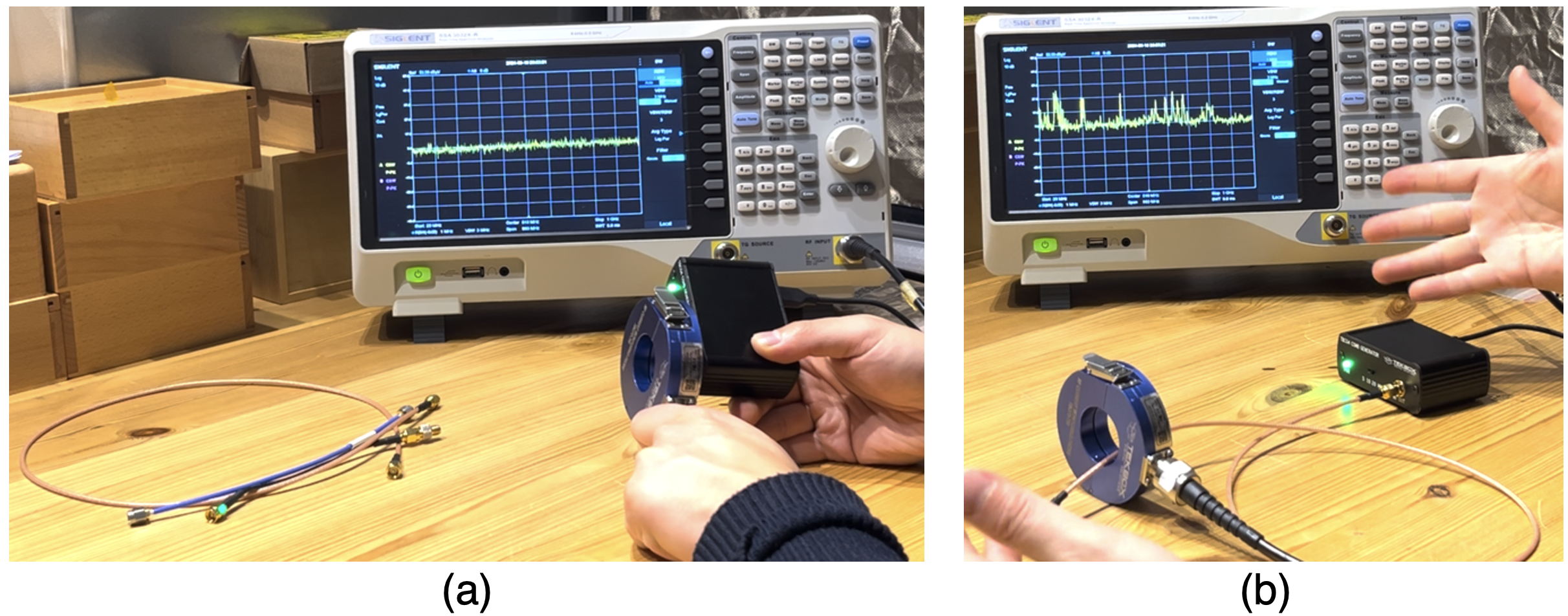
But here's an important check you need to perform: if the comb generator is not well shielded (i.e., if there is leakage), the field can couple to the outer sheath, causing RF current to flow on the outer shield. This would have nothing to do with the coaxial cable itself. Therefore, the first step is to check whether the comb generator is properly shielded, in this case, we connected the 50 ohm terminator to the output of the comb generator and used the RF current probe to see if there is any leakage, as shown in Figure 1 (a). The comb generator we used has great shielding performance by itself.

Figure 1 (a) Checking the leakage of the comb generator (b) The RF current probe picked up ambient noise
The set-up is shown in Figure 1(b). In this case, we set the spectrum analyser’s frequency range between 10 MHz and 1 GHz (with an RBW set to 100 kHz, no attenuation, and the pre-amplifier enabled). The comb generator produces pulses every 20 MHz, with a rising edge of less than 250 ps. The RF current probe is used to monitor the RF current.
However, the immediate issue we encountered, as shown in Figure 1(b), was the detection of significant ambient noise. This is inevitable without a shielded enclosure, as cables can pick up external noise. To address this, we propose the following adjustments:
Use a selected frequency band rather than the full span. For example, the 400-500 MHz or 900 MHz-1 GHz range.
Further reduce the RBW, in this case to 10 kHz(or lower), to lower the noise floor.
With these adjustments, we were able to perform the desired test. Figure 2 shows the results of three coaxial cables under test. We selected the frequency range of 400 and 500 MHz. As the comb generator has a frequency spacing of 20 MHz, you can clearly see the difference between a poorly shielded cable and a well-shielded coaxial cable.

Figure 2 Test results and comparison
In this short article, we’ve provided a cost-effective method for testing the shielding quality of coaxial cables.
Get more from EMC Standards
EMC Standards is a world-leading resource for all things EMC and EMI related. Our website is packed full of both free and paid-for content, including:
- Online quiz
- Webinars
- Training quiz
- And much more!

Electromagnetic Engineering (EMgineering) is the basis for proven good design practices for signal integrity (SI), power integrity (PI), and the control of EMI emissions and immunity (EMC).
Our aim is to help people learn how to more quickly and cost-effectively design and manufacture electronic equipment (products, systems, installations, etc.) to meet functional (i.e. SI/PI) specifications and conform to EMC standards, directives and other requirements.
Such equipment should benefit from reduced warranty costs and financial risks, whilst improving uptime, competitiveness and profitability.
We also cover basic good electrical safety engineering; and the Risk Management of Electromagnetic Disturbances / EMI, whether for Functional Safety or other types of risk.
Join EMC standards TODAY!
