Shielding and filtering don't work independently of each other
11 Jun 2018
I have lost count of the number of times I have been asked to fix an EMC problem, only to find that a shielding box has been designed or purchased to provide XdB up to fMAX, and a filter has been designed or purchased with a similar specification, but to reduce cost the filter has been mounted on a PCB inside the box with a cable from it entering or exiting the box through a plain connector.
Of course we want to reduce BOM cost – but at the expense of having to respin the design at least once and losing sales through delaying the time-to-market? I don’t think so!
The cable entering or exiting the box through a plain connector is simply an “accidental RF antenna” that couples unwanted EM noise between the inside and the outside of the shielded box.
This has little to do with the signals or power that the cable is meant to be carrying, but has everything to do with the fact that all conductors, whether electrical, mechanical or whatever, never mind their net names, never mind whether they have green insulation with a yellow stripe, always interact with their EM environments.
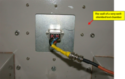
When filters are tested by their manufacturers, they are first carefully installed in absolutely the best shielded enclosure that their manufacturers can afford, such as in the photograph below. Does this looks like how the mains filter is installed in your new product?
The upshot is that filtering and shielding have to be designed together, as a system.
They simply cannot provide their shielding or filtering independently of each other.
The sad and stupid thing is that no filter manufacturer ever provides any information on what shielding is necessary for their filters to function as specified. So I guess it is understandable that designers who haven’t yet learnt the hard way – the very costly and time-consuming way – will assume that shield and filter specifications will be met by the shield and filters on their own.
SPICE and similar circuit simulators assume that electric and magnetic fields don’t exist, so they incorrectly tell us that a filter will achieve whatever its specification says, or circuit design achieves. Such over-simplistic simulators completely ignore what will actually happen in real life unless appropriate shielding is integrated with the filter.
I can only hope that some designers will read this brief blog, take the trouble to learn how to design shielding and filtering to work together to get the best out of both (takes a few hours, tops).
I hope they never have to repeat the horribly costly and time-delaying learning curve that so very many designers have gone through before them. There’s simply no point!
Get more from EMC Standards
EMC Standards is a world-leading resource for all things EMC and EMI related. Our website is packed full of both free and paid-for content, including:
- Online quiz
- Webinars
- Training quiz
- And much more!

Electromagnetic Engineering (EMgineering) is the basis for proven good design practices for signal integrity (SI), power integrity (PI), and the control of EMI emissions and immunity (EMC).
Our aim is to help people learn how to more quickly and cost-effectively design and manufacture electronic equipment (products, systems, installations, etc.) to meet functional (i.e. SI/PI) specifications and conform to EMC standards, directives and other requirements.
Such equipment should benefit from reduced warranty costs and financial risks, whilst improving uptime, competitiveness and profitability.
We also cover basic good electrical safety engineering; and the Risk Management of Electromagnetic Disturbances / EMI, whether for Functional Safety or other types of risk.
Join EMC standards TODAY!
